I put together the arduino protoshield from sparkfun. Excellent instructions at atomicsalad. Even though it’s a standard through-hole kit, atomicsalad’s instructions were nice to follow along.
After it was put together I had a few built-in LED lights to play with. I had seen this 555 timer in a piece kit I bought and I wondered what it does. I found a ton of examples and apparently you can do a zillion things with it. I wanted to start with the basics so I set out to make a light blink using only hardware. I’m only using the arduino for power in this one.
 I found a great tutorial on youtube and modified it to work on a larger breadboard. I had some trouble because it turns out that this breadboard has its power rails split down the middle. I was confused and stuck on this for a day. Eventually I found a video that hinted at this fact and connected the two sides like so. After that, the power rails on each side will work like I expected. This is by design on these boards so that you can have two different voltages but I found it annoying.
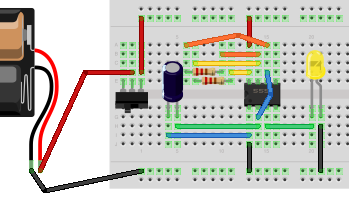
So here’s the schematic that I followed for the configuration on the big breadboard.

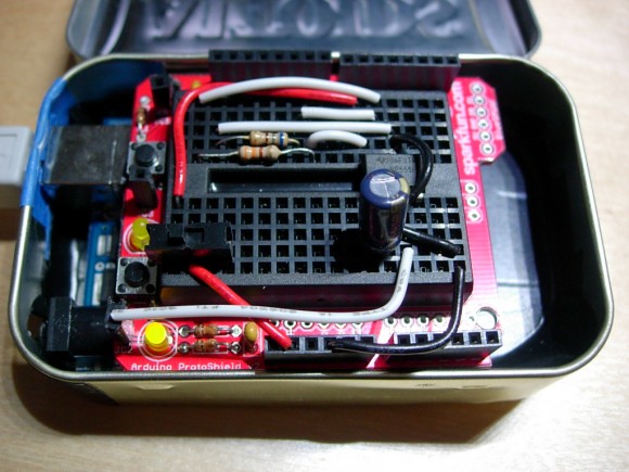
I transferred this layout onto a mini breadboard and it works like a champ. The protoshield has room for a mini self-adhesive breadboard. Here’s the actual wiring shot. This uses a light on the protoshield vs the light on the breadboard schematic. The concept is the same though. Pin3 on the 555 is the output which makes the light blink rapidly. You could use this chip as a cpu clock for example.

You don’t have to use the breadboard switch (the black thing on the left), it’s just more convenient to flip a switch rather than plug in/out of the 3v. Oh yeah it’s powered by 3v on the arduino. The cap is 100uf. You can use 2x orange,orange,maroon (gold) resistors or one of those and a blue,gray,maroon one (sorry I don’t have the resistance values). Play with the resistor values to change the blink rate.