Let’s take the magic out of networking, shall we?
First things first, let’s establish some ground rules:
- Our aim is to provide an abstraction level akin to that experienced by a Linux server or networking device user, not delving into the intricacies of network engineering.
- We’ll avoid nitty-gritty details of bits, electrons, and cables. After all, when people say they don’t grasp networking, they’re usually not referring to the physics behind it.
- Our model won’t operate within an event loop. While scripting or CLI tools are fantastic, they’re inherently limited by their sequential nature. Real-world networking operates asynchronously, akin to a bustling city where events occur in parallel. To replicate this, we would need to veer into text-mode game territory, and I don’t want to do this. We can learn about networking without making a long-running program but some things will need to be faked.
Now that we’ve set some boundaries, let’s name some exciting topics ahead. We will explore bit-math, frames, packets, understand different abstraction layers, make a binary file that can actually be read by Wireshark and create a working local area network (LAN) using real specifications.
This is a series of posts exploring networking by building things:
- Part 2 - implements primitives like IP, ARP and an Interface
- Part 3 - finishes the abstractions and shows the whole thing working
For more in-depth background, here is a nice video series but I encourage you to replicate my work and build a network yourself in Rust or some other language. You’ll learn more by doing.
Approximately How Networking Works
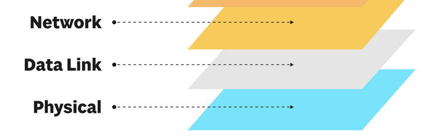
Networking works in abstraction layers from the point of view of the OSI model. From the bottom up, it goes (1) Physical, (2) Data Link and then (3) Network layer. It continues to higher abstraction layers but our simulation and this blog post series will stop at layer 3.
Imagine a server named box1 pings box2.
user@box1 $ ping box2
The ICMP program ping is way up at layer 7 (not pictured below) and sends information down the left side of the picture below ICMP client -> IP -> Ethernet -> Switch Port 1. Eventually it turns into bits, electricity that flows across the switch through cables (not pictured) and then hits box2’s stack where it flows back up right side. This flow up the right side of the picture is shown below as Switch Port 4 -> Ethernet -> IP -> ICMP client. (The ICMP responder would really a part of the network stack on box2). So notice that the flow down the left side and the flow up the right side are opposite and reversed.
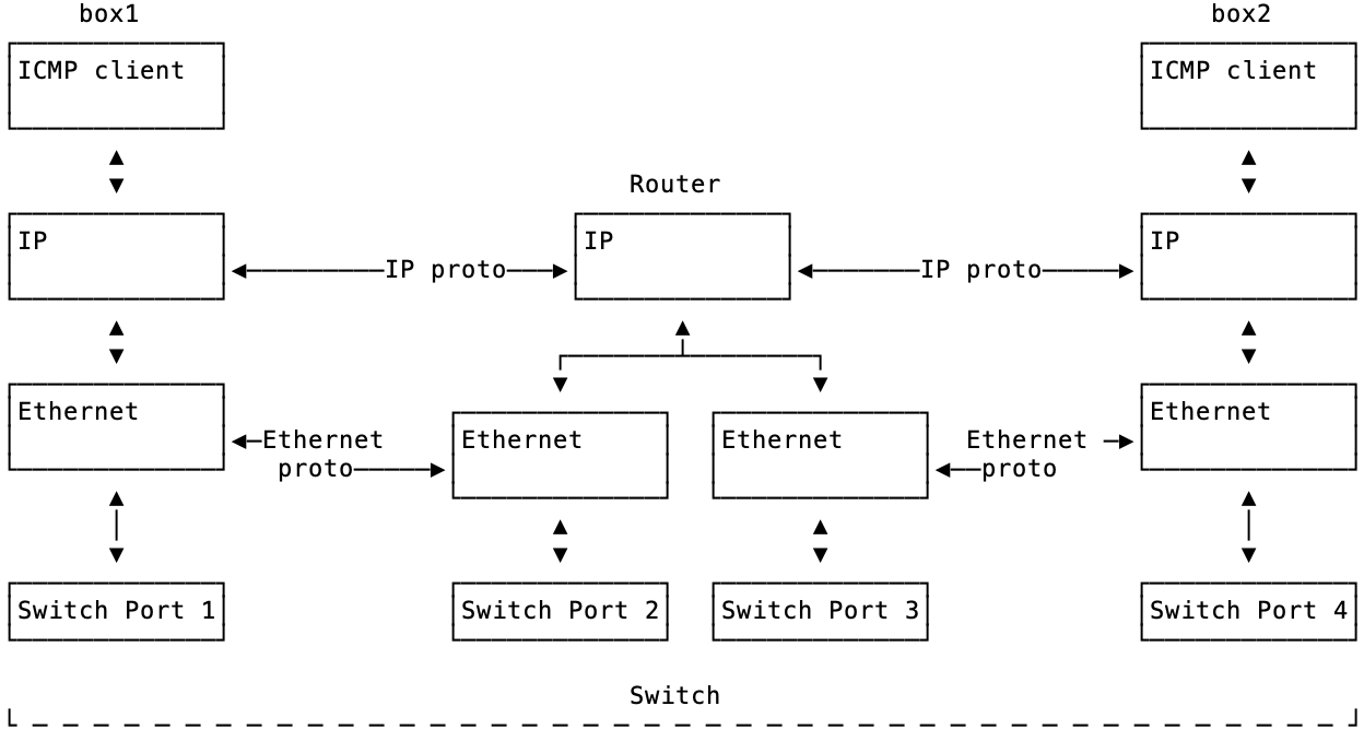
We will talk about all the details of all of this. But here are key takeaways at this point:
- Details are hidden by the abstraction layers.
- The layers are different. The physical layer could be copper wires, wifi, pigeons or glass. The other layers don’t know or care. Ping works the same over wifi or wires.
- Each layer has its own concerns (non-leaky abstraction).
Examples in the World
You’ve probably seen some of these concepts in terms of things you interact with like ip addr or ifconfig or a network cable. So, the point of this simulation is to try to model things around these common interactions and see if we can fake ping box2.
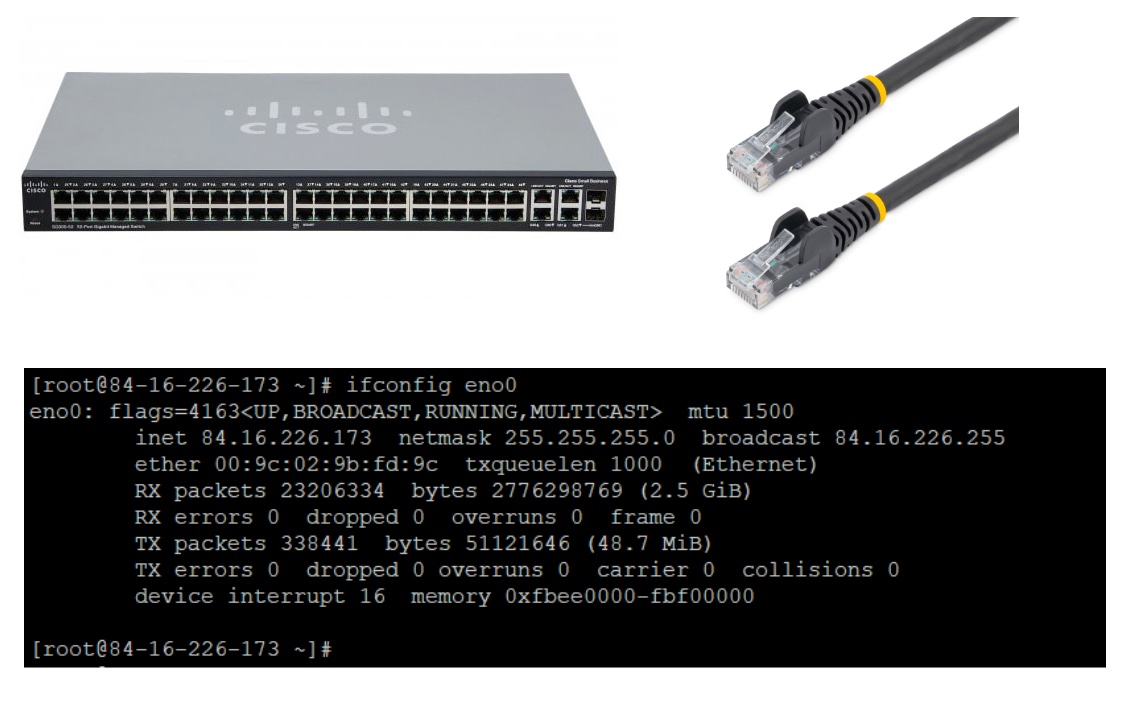
Take a look at the # ifconfig eno0 output above. This command has been replaced in many Linux distributtions with ip addr but the output is basically the same. The IP address is listed as inet 84.16.226.173. The netmask is 255.255.255.0 and the MAC address is under ether 00:9c:02:9b:fd:9c. The output for ip addr will be slightly different.
So in terms of modeling and the previous layer diagram, we will probably need at least the following nouns/objects/concepts/structs:
- A server called
box1with an IP address. It could be84.16.226.173but we will use a more common private IP address of192.168.0.1. - An IP address. Something that represents an IP. We won’t rebuild
ip addrorifconfigso we’ll need to make an IP address “thing” and a subnet mask. - An Ethernet device. Notice that in the ifconfig screenshot the interface is called
eno0. The device name is arbitrary depending on your device driver and hardware model. We’re not going to model device driver details, all we need is an interface with a MAC address. The MAC address is burned onto a network card at manufacturing time. The MAC’s job is to locally identify an interface (sometimes called a NIC) on a local area network (LAN). - You’ve seen Ethernet cables. We won’t end up modeling cables but you’ve probably noticed the plug on a switch or a home router. You’ve also probably noticed that when you plug in a port a light turns on.
Notice that we can sort the things we have named so far into the same abstraction layers.
- Layer 1 / Physical - Cables, ports on a switch, pins, bits, electricity
- Layer 2 / Data Link - Ethernet, MAC addresses, a link light
- Layer 3 / Network - IP address, subnet mask, the ICMP protocol which ping uses
- Layer 7 / Application - A program named
pingin Linux and Windows
Notice that we skipped nnumbers 4, 5 and 6. This is on purpose because these layers do not have concepts we have named. We can just ignore them for now for simplicity. We are going to focus on Layers 2 & 3 while faking Layer 1.
Starting our Model
So, with these concepts named and sorted, we can start thinking about how to implement this. There are many ways to implement all of this. First, I arbitrarily selected Rust because it’s my current low-level, CLI type of language. It’s also nice to have access to bytes and tooling that is lower down in abstractions. Specifically, we’ll be using a library called etherparse to avoid us having to define binary bit offsets from the specs and things like that.
First, let’s talk about the end-to-end flow of what happens with ping and then we’ll discover some things. When user@box1 $ ping box2 executes, this is approximately what happens:
- Before anything happens, we had already created our network. IE: bought two servers, a switch and some cables.
- We plugged in box1 into port1 and box2 into port2 on an ethernet switch.
- The interfaces came with a MAC burned in at manufacturing time.
box1has11:12:13:14:15:16. Each hex for box1 starts with1for ease of reading for the reader. - We assigned
192.168.0.1to box1. It ends with.1for ease of reading for the reader (and myself). - We did the same for
box2with192.168.0.2and the MAC21:22:23:24:25:26.
When ping fires,
- The program
pingcreates an ICMP packet and tells the network stack to make an ICMP packet with the destination of box2. This is layer 3. - The ICMP packet destiation of
box2isn’t good enough. It needs an IP address. So, before the IP packet is made, it looks up the IP address forbox2. Normally, this would probably be done with DNS. We are going to fake it with a fake hosts file. - The IP layer now crafts a packet with the source of box1’s IP address and the destination IP of box2.
- The IP layer now finds the interface that this network packet needs to go out on. Our simulation will only have one interface per server.
- Now we hit layer 2. The IP is not enough, we need to put this network packet on the Ethernet network. So, we have to make an ethernet frame. The ethernet frame has a source and a destination just like IP does but it speaks in MAC addresses, hardware locations.
- The server goes through a process of resolving the MAC address with a protocol called ARP which asks the network who owns the IP for
box2 (192.168.0.2). ARP replies with21:22:23:24:25:26. Now,box1remembers this information in its ARP cache. - Now
box1sends the Ethernet packet out its interface to the switch on port 1.
This is where the simulation implementation ends. The switch in this example is a dumb layer 2 switch that hasn’t seen any traffic from anybody. All it has seen is an Ethernet packet coming from port 1 with a destination of 21:22:23:24:25:26. It doesn’t know where 21:22:23:24:25:26 is. So normally, it would flood all ports trying to find who that is. For our example, we stop here. If we implemented the switch some more, we would pass the ethernet frame into the interface attached to port 2.
There are many ways we could have modeled this but for now, this is enough. Notice that we have run into some concepts here like box, IP, switch, MAC, ARP and some others. These are some of the things that we will start modeling.
Our first model, the MAC address
A MAC address is what was in the ether field from the ifconfig screenshot we saw earlier. It’s a series of bytes in hex. An ethernet device has one but also dumb switches use them for passing along packets. We’ll talk about switches more in later posts but for now know that we have at least two things that need to know about MAC addresses. Without explaning each one now, these are the things we will find out that we need to have MAC addresses for:
- An ARP broadcast asks the local network if anyone knows about the ownership of an IP address
- A switch keeps a copy of MAC addresses it has seen in a table called a CAM table
- An ethernet interface has its MAC address usually burned onto a ROM
So, this MAC address concept is coming up a lot. We should model a MacAddress type. We’ll also want to print this out in a friendly format for debugging so we will make a .to_string() method.
pub type MacAddress = [u8; 6];

pub fn to_string(mac: &[u8; 6]) -> String {
    // Convert each byte to a two-character hex string and join them with colons
    mac.iter()
        .map(|byte| format!("{:02x}", byte)) // Ensure two digits with padding if necessary, and lowercase hex
        .collect::<Vec<_>>()
        .join(":")
}

pub fn parse_mac_address(mac: &str) -> MacAddress {
    let parts: Vec<&str> = mac.split(':').collect();
    if parts.len() != 6 {
        panic!("Invalid MAC address format");
    }

    let mut mac_array = [0u8; 6];
    for (i, part) in parts.iter().enumerate() {
        mac_array[i] = u8::from_str_radix(part, 16).expect("Invalid hex value in MAC address");
    }
    mac_array
}


#[cfg(test)]
mod tests {
    use super::*;

    #[test]
    fn test_parse_mac_address_valid() {
        let mac_str = "AA:BB:CC:DD:EE:FF";
        let expected = [0xAA, 0xBB, 0xCC, 0xDD, 0xEE, 0xFF];
        assert_eq!(parse_mac_address(mac_str), expected);
    }
}
The tests section shows its usage. It will be more useful and clear what this type is doing when using it with an interface or an ARP function. But for now, that’s our first model. The others will be similar.
In the next post, we’ll continue modeling out concepts. The source code will not be completely explained and duplicated in following posts but is available on Github.